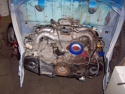
Saturday, November 7, 2009

42) Alternator belt

Photo

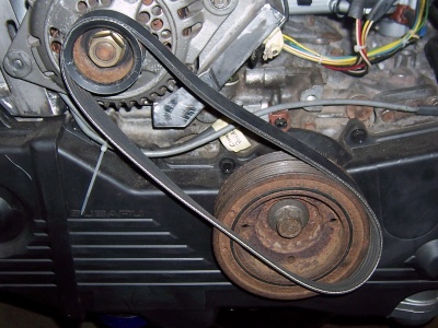
With the new alternator bracket in place, I now had a bit of an issue with finding the right belt that would fit. This belt was too tight, and wouldn't fit with the alternator adjusted as low as it could go. The next belt size up was too long and the alternator didn't have enough adjustment to make it tight.

Photo

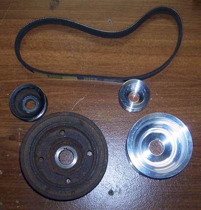
I then decided to get a set of smaller pulleys to see if my smallest belt would fit.

Photo

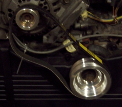
No luck, the smallest belt now is too big for these small pulleys.

Photo

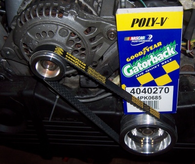
I finally found a belt that was the perfect length, and allowed me to tighten it right about midway through the adjustment of the alternator! The only possible problem here is that this belt has skinnier then the OEM belt. I'm guessing that since this is only driving the alternator that it should hold up fine :) *Fingers Crossed*

Labels: ,

Thursday, January 22, 2009

36) Coolant manifold

Photo

The coolant manifold got the same treatment as the intake manifold. You can also see here the outlet (top right) has been cut and re-welded to be shorter and now fits when bolted down in it's new flipped position.

You can also see on the bottom left a fitting for one of the heater connections. I ended up removing the steel tube that was originally bolted to the manifold, and tapped the hole for the NPT fitting.

Photo

You can see here how it fits under the intake manifold. The heater hose will go in between the intake runners.

Photo

Here's a quick show of how it all looks bolted up : )

Labels: , ,

Saturday, May 10, 2008

34) Intake planning

Photo

Got some parts for the intake here. I also found a nifty little adapter to go from my mass air flow meter, back to a 3" pipe. This is where I'll put on some sort of a cone filter. I've got an old one laying around here, so I'll first try that. Here you can also see some silicon tubing that I'll use for the connections needed to the intake. The two little plastic bags there have some tube barbed fittings that I'll use to attach the tube to the shinny L bends.

Photo

Here's the first mock up. You can see that I didn't need my long straight piece. And I also picked up a 90 degree silicon bend to fit on my throttle body. While I was setting this all up, I kept closing the deck lid to make sure it all fits. So the air filter in the back will need a bracket to bolt it up to the firewall. I'm also thinking about using one of those "bubble" silicon joints instead of the straight joint there. This way when the engine moves it will allow the intake to move separately.

Labels: ,

Saturday, April 12, 2008

32) Intake and coolant manifold mock up

Photo

After cleaning the engine, I started messing around with intake positions. Putting the intake on the stock way makes the throttle body point directly at the firewall. I don't want to cut the firewall, so I needed to find a better way. Thankfully the Internet has many Subaru -> Beetle projects, and I found that you can flip the intake 180 degrees! Works great, except I see that the stock intake piping is too big and will hit the decklid. My plan here will be to get some 90 degree pipe bends, and a 90 degree silicon elbow to connect to the throttle body. (More pictures to come)

Photo

Here is the other side. You can also see the coolant manifold has also been flipped around 180 degrees. This will make for nicer piping location to the front of the car. I didn't want to have to pipe from the rear of the engine and down past the exhaust. My plan is to use aluminum tubing and radiator hose to go from below the right axle, inside to the center channel and out the front of the car from the middle of the beam. Stay tuned for pictures of the whole thing!

Labels: ,

Monday, April 7, 2008

30) How it got there

Photo

I wanted to show the adapter plate, and how this Subaru engine bolts to the Beetle. This show is of the KEP adapter plate bolted to the engine. The studs are installed to slide right into the VW transmission. All the hardware came with the kit: Adapter, flywheel, nuts & bolts.

Photo

This is with the KEP flywheel bolted into place. This allows the VW clutch, and the VW starter to mate right up! (Notice the little flywheel lock on the upper right. Makes life a little easier when torquing down the bolts)

Photo

I elected to buy a stage 1 clutch / pressure pate from KEP. Here is the clutch matted up to the flywheel. The kit even came with the alignment tool that you can see in the center.

Photo

And finally here is the pressure plate bolted up and torqued down. Be sure to tighten slowly and in a star patter here, as you can bend the pressure plate if done incorrectly.

Photo

I also wanted to show a picture of the VW transmission all ready for the engine. I got a new bushing and throw out arm. The clutch kit also came with a new throw out bearing you can see here.

Labels: ,

Wednesday, April 2, 2008

29) It fits!

Photo

Here is the Subaru EJ22 all bolted up and the body temporarily back down on the chassis. This thing fits in there without any modifications to the body. (Note: I will need to modify the rear apron a bit for it to fit around the timing belt cover) I bolted the engine in with a Kennedy (KEP) adapter plate.

I can see now that there are a couple of items to address here. First of all the throttle body is pointed right at the firewall. I will rotate the entire intake assembly around 180 degrees. Secondly the coolant manifold is pointed strait towards the back of the car. I will flip that around 180 degrees. This will have to be cut and re-welded to clear the crank case (Pictures to come).

Labels: , , ,

Monday, February 25, 2008

27) Test fitting rear suspension

Photo

I am finally far enough along on the metal work, that I've starting to do some test fitting! This is one of the rear trailing arms bolted up with the adjustable spring plate, and aluminum cover. Everything fit, except the two adjuster bolts on the spring plate. To get the clearance I needed, I shaved the forward most bolt, and welded it right to the spring plate. The adjuster bolt I cleared out the metal area behind to give plenty of area for a wrench to adjust.


Photo

Here is the other side with the wheel mounted up. I wanted to see how much wider the new setup would be.


Photo

Here is the extra width that I will have to deal with. To make this car look right, I think I will have to get some extra wide fenders. I know Creative Car Craft makes very good quality fenders.

Labels: